VRV IV Water Cooled
-
Available inHeat Pump or Heat Recovery
-
Capacities16kW-101kW
-
RefrigerantR32
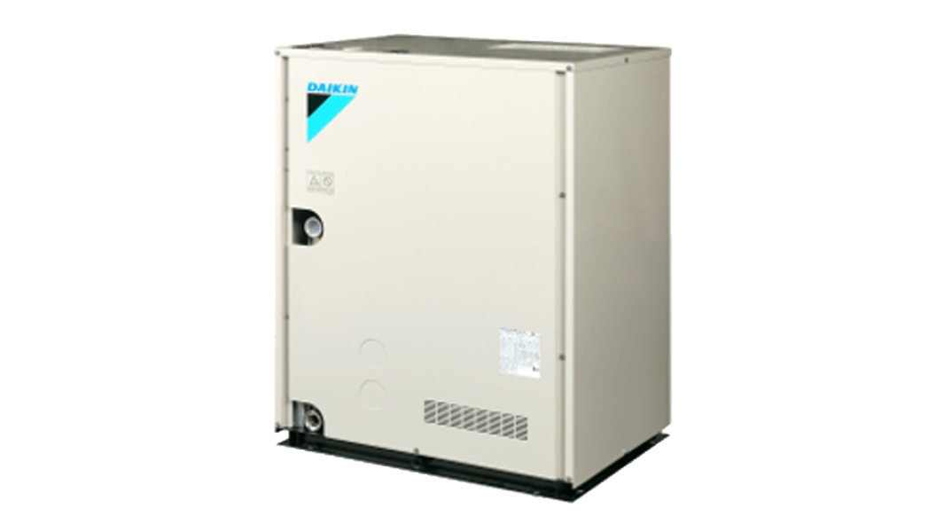
Daikin VRV IV Water Cooled (VRV IV-W) is an individual air conditioning system that utilities water as a heat source. In this unique system, water is piped from a central cooling tower or boiler to the compact VRV IV-W unit (the equivalent of the outdoor unit/condenser in a conventional air conditioning system) and after heat exchange, refrigerant is piped from the VRV IV-W unit to each indoor unit.
This unique system allows this condenser to be placed inside the building, which greatly extends design flexibility and makes it easier to adapt to creative building facades where air cooled VRV solutions are not possible. Furthermore VRV IV-W can perform as a heat pump or heat recovery system to suit the requirements of most commercial applications.

Minimum Energy Performance Standards
Features
- Unified heat pump or heat recovery (simultaneous operation) condensing unit
- Variable Refrigerant Temperature "VRT" technology for improved energy efficiency and comfort
- 16kW, 22.4kW, 28.0kW & 33.5kW condenser modules available that may be combined for a maximum capacity of 101kW
- Continuous operation for cold climates, delivering comfortable heating performance with no defrost
- Long refrigerant lines of up to 120m (linear run) and a total of 300m
- Plate Heat Exchanger can withstand a maximum water pressure up to 30kPA (for water design water flow rate of 1.6L/s)
- Allows for a maximum connection ratio of 130%
- Condensers are compact 780x550x1,000mm (WxDxH), lightweight - 146kg (16kW class) and can be double-stacked to minimize spatial requirements
- The advanced self-diagnostic auto-check function detects malfunctions, immediately displaying the fault type and location so it can be resolved quickly and effectively
- Condensing unit sound level as low as 49dB(A)
- Connects to all advanced Daikin Control Solutions including I-Touch Controller and I-Touch Manager
- Can be integrated to Open Protocol Building Management Systems via the Daikin BACnet® and LonWorks ® interfaces
Advanced features for easy installation and superior reliability
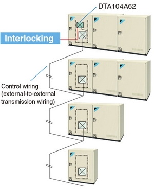
- VRV IV-W features a pump interlock function, controlling the heat source pump in parallel
with the starting of the VRV IV-W unit, significantly simplifying operation and management of a
buildings air conditioning system. - VRV IV-W uses DIII-NET - Daikin's proprietary high speed transfer protocol.
DIII-NET means all indoor units, VRV IV-W units and control systems can share common wiring, making installation easier. - VRV IV-W can also be easily connected to existing third party BMS systems via Daikin DIII Net.
- VRV IV-W includes an auto address setting function and check function to detect and flag wiring and piping connection errors, for easier installation.
- Water piping goes only to the VRV IV-W unit, with refrigerant piping run in occupied spaces. This means there is virtually no risk of water leakage or corrosion damaging interior fit out.
Centralised interlocking function
VRV IV-W allows centralised interlocking input via an external control adaptor (DTA104A62).
By using one external control adaptor circuit board, centralised interlocking input to multiple units within the same water system is possible.
By adding suction gas piping and a BS unit (sold separately), simultaneous heating and cooling operation can be provided by a single system.
 Heat Recovery
* For indoor units used for cooling only (do not connect to BS unit when using for heat recovery), total capacity index must be 50% or less than the capacity index of the outside units.
Water-Side Infrastructure & Components
- A water loop system is routed around the building, either vertically or horizontally.
- Heat Injection (Boilers) and Rejection (Cooling Tower or Dry Coolers) are required to ensure that the water loop remains between the required design conditions of 10-45°C.
- VRV IV-W condensers are connected to the water loop and the connecting refrigerant circuit serves indoor units the same as any air cooled VRV system.
The following Water Side components are required:
- Strainer (Mandatory)
- Flow Switch or Differential Pressure Switch (Mandatory)
- Pressure and temperature gauges
- Circulation Pumps
Heat Recovery
Heat Recovery
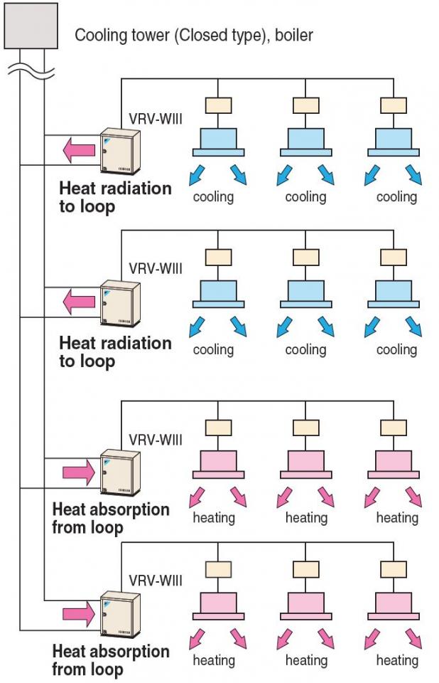
VRV W III offers 2-stage heat recovery operation.
The first stage is within the refrigerant system itself. By incorporating a BS unit that switches cooling and heating into the system, VRV W III can provide simultaneous cooling and heating to different areas in the same building, with heat recovery performed between indoor units.
The second stage is within the water loop, where heat recovery is performed between the actual VRV W III systems.
This 2-stage heat recovery operation substantially improves energy efficiency, making VRV W III the ideal solution to the requirements of modern buildings where some areas may require year round cooling, depending on the sunlight exposure, the number of occupants and other factors which may affect indoor temperature.
Stage 1:
Simultaneous heating and cooling within the refrigerant system.
In mainly cooling, partly heating mode, VRV W III recycles heat exhausted from cooling operations to heat another area. In mainly heating, partly cooling mode, the system uses cooled post-heating operation refrigerant to cool another area. This simultaneous operation greatly improves energy efficiency across the entire system.
The first stage: Between indoor units
A
Heat radiation
(all cooling)

Heat radiation operation (all cooling operation)
B
Heat radiation tendency heat recovery
(mainly cooling, part heating)
C
Heat recovery
(cooling and heating)

Heat recovery operation (cooling and heating operation)
D
Heat absorption tendency heat recovery
(mainly heating, part cooling)

Heat absorption tendency heat recovery operation (mainly heating, part cooling operation)
E
Heat absorption
(all heating )

Heat absorption operation (all heating operation)
Stage 2: Heat recovery operation between VRV W III systems.
Heat recovery operation is also available between systems connected to the same water loop, with systems exchanging heat via water. This greatly increases energy efficiency.
The second stage: Between VRV W III systems
Range
|
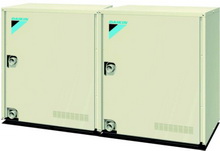
8, 10 Class |
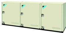
16, 18, 20 Class |
24, 26, 28, 30 class |
 |
 |
 |
|
RWEYQ8PY1 |
RWEYQ16PY1 |
RWEYQ24PY1 |
Technology
Innovative Water-Cooled Technology
Daikin water cooled VRV air conditioning systems offer a viable alternative to water-source heat pump solutions. Each connected indoor unit can provide heating or cooling independently to suit zone requirements, making these systems suitable for both open plan spaces and individual zones with varying temperature requirements.
1. Brazed plate heat exchanger
2. High efficiency compressor
3. Smooth sine wave DC inverter
4. Integrated water loop control
5. Compact design

Brazed plate heat exchanger
Refrigerant-to-water heat transfer is accomplished using a high efficiency, brazed plate heat exchanger. Water pressure drop through the heat exchanger is minimized, and an industry leading water temperature range allows for entering water temperatures as low as 15°C in cooling and heating.
The brazed plate heat exchanger also enables a much more compact design over other types of heat exchangers, contributing to VRV-WIII's small footprint.
High efficiency compressor
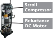
Daikin’s unique scroll compressor minimizes heat loss and is driven by a high efficiency motor to achieve significant energy efficiencies.
Smooth sine wave DC inverter
By adoption of the Sine Wave, which smoothes the rotation of the motor, operation efficiency is greatly improved.
Integrated water loop control
An integrated operational output allows the water cooled VRV-WIII system to energize and de-energize pumps or open and close isolation valves when the system is not in operation. An integrated flow proving input provides an interface for a water loop flow meter to ensure the system’s compressors do not operate if there is a loss of flow in the water loop.
Compact design
The water-cooled VRV-WIII design is based on a modular concept; all water-cooled condensers are of the same dimensions, and are available in 22kW and 27kW modules. With a footprint of only 0.43 metres square, a height of only 1,000mm, and the ability to stack modules, an 80kW system requires only about 0.95 square metres of floor space.